Home›Blog ›Alternative method of high-voltage power supply on image intensifier
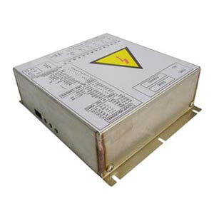
Alternative method of high-voltage power supply on image intensifier
The alternative method of high-voltage power supply is as follows:
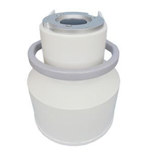
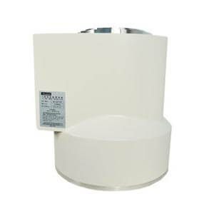
1. Remove the original high-voltage power supply, and be careful not to lose the mark on the original image intensifier connected to the high-voltage power supply.
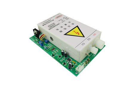
2. Install the new high-voltage power supply in the original location.
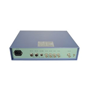
3. After checking that the original 24V DC power supply voltage is correct, insert the original 8-core flat wire plug into the 8-core socket of the new power supply. Pay special attention to the red wire in the 8-core flat wire plug to align it with pin 1 (+24V) of the socket. Can’t plug it back in!
4. Replace the HV, G3, G2, G1 high-voltage wires with the high-voltage cap of the new high-voltage power supply, put the original gasket and the 0-type gasket, and then insert them into the corresponding gasket. High-voltage output connector, and then close the new high-voltage cover.
5. The original wiring and markings of the high-voltage power socket should match and cannot be inserted incorrectly.
6. Insert the cathode PC and the ground wire GND into the corresponding sockets. After checking, you can boot.
7. G1 is the edge focus of the image and usually does not need to be adjusted; G3 is the image size adjustment (if there is no comprehensive test card, please do not adjust at will); because the HV high voltage involves the stability and safety of the power supply, it has been adjusted before leaving the factory. It has been adjusted, usually not adjusted!
When inputting +24V power, pin 1 is connected to +24V, and pin 2 is connected to 0V. At this time, the high-voltage power supply is working in the 9’state; adjusting G21 can adjust the focus of the image. When pin 6 A is connected to pin 4 E, its value is 6′: adjust G22 to adjust the focus of the image. When pin 5 B is connected to pin 4 E, it is 4′: adjust G23 to adjust the focus of the image.
The above are the parameters and replacement methods for installing the high-voltage power supply. As long as everyone strictly abides by this procedure, I believe that you can replace and debug the high-voltage power supply yourself. If you have any questions, please contact us!
Author:Lillian
Product Category
News
- Beyond the Basics: Understanding High-Voltage Cables for X-Ray Machines (75KV & 90KV)
- Elbow 75KV High Voltage Cable: The Hidden Backbone of Reliable X-Ray Machine Performance
- NK-15XZ-Ⅱ 6-inch X-Ray Image Intensifier: The Quiet Workhorse of Real-Time Imaging
- Why Are X-ray Image Intensifiers Falling Behind?
- Real-World Case Study: NK5761-TA Power Supply Replacement for Thales TH9464 6” Image Intensifier
Contact us
Tel: (+86) 18953679166
Whatsapp: +86 18953679166
Email: service@newheek.com
Company: Weifang Newheek Electronic Technology Co., Ltd.
ADD: E Building of Future Star Scientific Innovation Industrial Zone of No.957 Wolong East Street, Yulong Community, Xincheng Sub-District Office, Weifang Hi-tech Zone, Shandong Province, China